Thursday 21 September 2023

C02: Network Protocol

 An established set of guidelines that govern how data is transferred between various devices connected to the same network is known as a network protocol

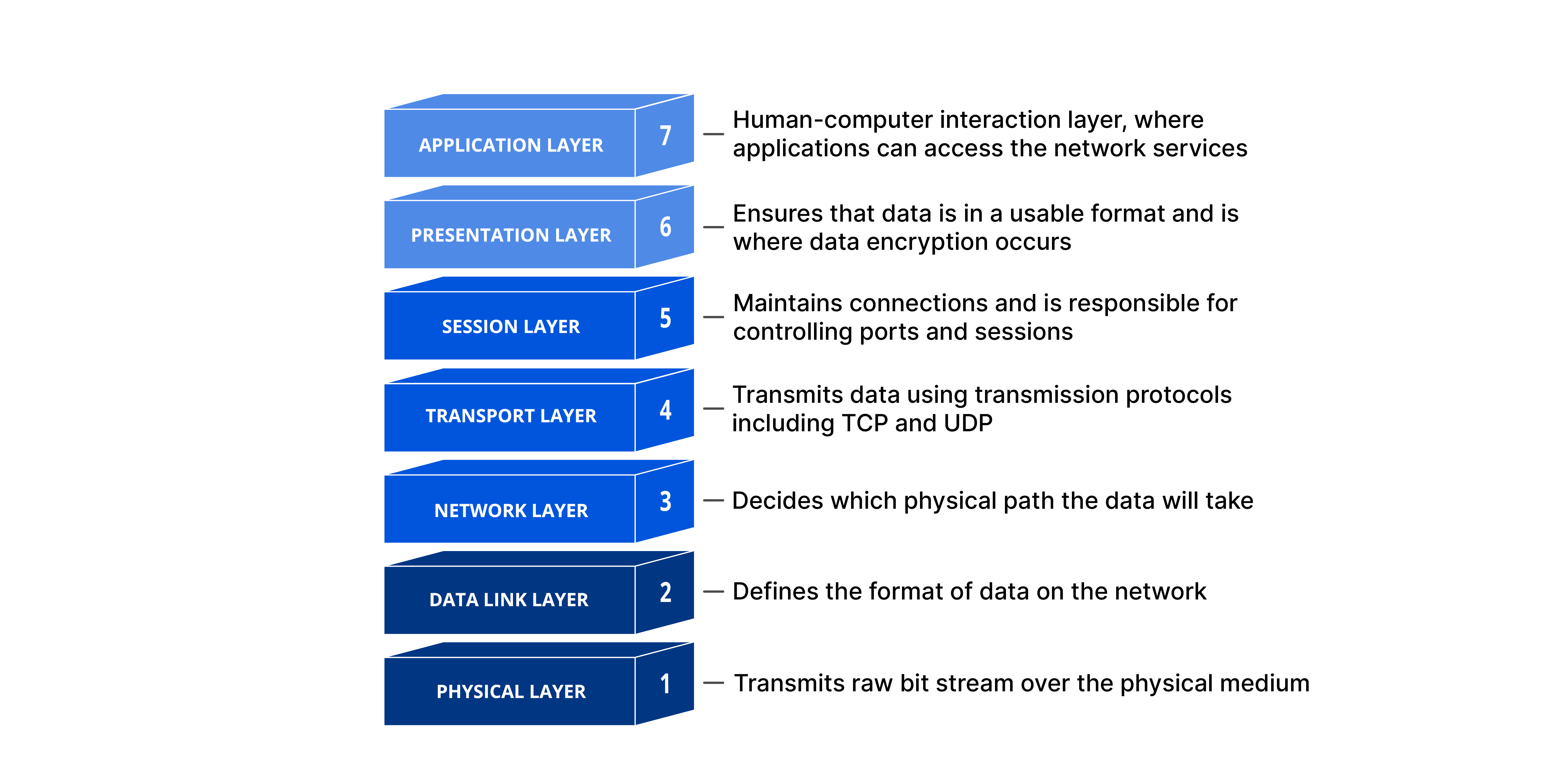
At the top of the OSI model is the application layer. Users interact with each other through this layer. The user receives services from it. Any kind of application or communication process requires the performance of a variety of functions by the application layer.

Application Layer Protocol

1. HTTP

  • HTTPS, which stands for Hypertext Transfer Protocol Secure, is the more secure form of HTTP, which is what HTTP stands for.
  • Data from the World Wide Web is accessed via this protocol. 
  • Pages in a text document are linked together using the well-organized documentation system known as hypertext.
  • The client-server concept is the foundation for HTTP.
  • It establishes connections using TCP.
  • Due to the statelessness of the HTTP protocol, the server does not keep track of the client's prior requests.
  • For connection establishment, HTTP uses port 80.
2. FTP
  • File Transfer Protocol is referred to as FTP. 
  • The protocol is what allows us to transfer files. 
  • Any two machines using it can facilitate this. FTP, however, is both a program and a protocol.
  • FTP encourages file sharing between distant computers through dependable and effective data transfer. For FTP, the data port is 20 and the control port is 21. 
3. DNS
  • Domain Name System is what it stands for. 
  • Therefore, a DNS server must convert each time a domain name is used into the corresponding IP address. 
  • The translation of www.abc.com, for instance, could be 198.105.232.4. 
  • 53 is the port number for DNS. 
4. SMTP
  • It stands for Simple Mail Transfer Protocol.
  • A component of the TCP/IP protocol, it. 
  • SMTP transfers your email on and across networks by use of a procedure known as "store and forward." 
  • To get your communication to the appropriate computer and email inbox, it closely collaborates with a component known as the Mail Transfer Agent (MTA). The SMTP port number is 25, and it. 
5. POP
  • POP stands for Post Office Protocol, and POP3 (Post Office Protocol version 3) is the most recent version. 
  • User agents utilize this straightforward protocol to retrieve messages from mail servers. 
  • POP protocol operates on port 110.
  • It establishes connections using TCP.
  • POP operates in two modes: Keep Mode and Delete Mode.
  • Once the messages have been downloaded to the local system, the Delete mode deletes them from the mail server. 
  • Keep mode allows users to read their emails from the mail server at a later time while without deleting the message from the mail server.
6. Telnet
  • Telnet stands for the TELetype NETwork.
  • In terminal emulation, it is helpful. 
  • It enables Telnet clients to access the Telnet server's resources. 
  • On the internet, it is utilized for file management. Devices like switches are first set up using it. 
  • The telnet command is a command that connects to a remote system or device using the Telnet protocol. Telnet uses port number 23. 
Transport Layer
  • In the TCP/IP model, the transport layer is the second layer; in the OSI model, it is the fourth layer. 
  • In order to deliver messages to a host, it is an end-to-end layer. It is referred to as an end-to-end layer since it offers a point-to-point connection between the source host and destination host rather than a hop-to-hop connection to deliver the services effectively. In the Transport Layer, a segment is the basic unit of data encapsulation. 
  • From the perspective of the sender, the transport layer receives data (messages) from the application layer, splits the data, adds the source and destination ports to the header of each segment, and sends the message to the network layer.
  • The transport layer receives data from the network layer, segments it, reads its header, determines the port number, and then passes the message to the correct port in the application layer.

1.UDP
  • A Transport Layer protocol is called User Datagram Protocol (UDP). 
  • The Internet Protocol family, also known as the UDP/IP suite, includes UDP. It is an unreliable, connectionless protocol, unlike TCP. Therefore, there is no requirement for a link to be established before data transfer. Low-latency and loss-tolerant connections can be established over the network with the aid of UDP. Process to process communication is made possible through UDP. 
  • Process to process communication is made possible through UDP.


Network Layer Protocol

ARP
  • The media access control (MAC) address of a device is one example of a physical address to which an IP address can be mapped using this protocol. 
  • This enables networked devices to communicate with one another.
RARP
  • A physical computer in a local area network (LAN) can utilize the Reverse Address Resolution Protocol (RARP) to ask for its IP address. 
  • This is accomplished by transmitting the device's physical address to a dedicated RARP server on the same local area network (LAN) that is watching for RARP requests.
ICMP
  • Between devices on a network, this protocol is used to send error messages and other types of information. 
  • It is frequently used to provide diagnostic data or troubleshoot network problems.
IGMP
  • It stands for Internet Group Message Protocol
  • Two types of communication:
    • Unicasting - One-to-one communication
    • Multicasting- One-to-many communication
  • It is used by the hosts and router to support multicasting and moreover to identify the hosts in a LAN.
IP
  • It is a set of rules for routing and addressing packets of data
  • The information in IP is attached to each packet which helps router to send packets to the right place.
  • Once the packets arrive at their destination, they are handles differently depending on which transport protocols is used in combination with IP.
  • Types of IP Address:
    • Static IP address  is the one which is manually created as opposed to having been assigned and cannot be change.
    • Dynamic IP address is the one which is assigned by Dynamic Host Configuration Protocol (DHCP) server and it can be changed.
  • Classes of IP address: IP address defines five classes ; A, B, C, D and E each having range of valid IP addresses. The first three IP address can be used as host address and the last two are used for multicast (D) and for experimental purpose (E).
Class A IP address has the first octet starting from 0.
Class B starts from 0+128 = 128. 
Class C starts from 0+128+64=192. 
Class D starts from 0+128+64+32=224. 
Class E starts from 0+128+64+32+16=240.


Class A ends at 127, which can be inferred from the starting end of Class B. 
Similarly Class B ends at 191.
Class C ends at 223.
Class D at 239. 
Class E at 255.

Network Access Layer
  • The TCP/IP protocol hierarchy's Network Access tier is the bottom tier. 
  • The protocols in this layer give the system the tools to send data to the other gadgets on a network to which it is directly connected. It specifies how to send an IP datagram over the network. 
  • In contrast to higher-level protocols, Network Access Layer protocols need to be aware of the specifics of the underlying network (its addressing, packet structure, etc.) to format the data being transferred in a way that complies with network requirements. 
  • All of the operations performed by the Data Link and Physical layers at the bottom of the OSI reference model can be included in the TCP/IP Network Access Layer.
Ethernet
  • The standard method for establishing connections between devices in a wired LAN or WAN is Ethernet. 
  • It allows for the use of a protocol, which is a set of guidelines or common network language, to allow devices to communicate with one another.
Ethernet Types
1. Fast Ethernet: Supported by twisted pair which is quite a high-speed internet and can transmit or receive data about 100Mbs.
2. Gigabit Ethernet:   Data is transferred over this type of network at a rate of roughly 1000 Mbps or 1Gbps. Fast Ethernet is being replaced with Gigabit speed, which is an improvement. The data transfer speed in this kind of network is influenced by each of the four pairs in the twisted pair cable. 
3. 10-Gigabit Ethernet: With a data transfer rate of 10 Gigabit/second, this form of high-speed network is even more modern and efficient. This network area can be expanded up to about 10,000 meters by employing a fiber optic cable.
4. Switch Ethernet: This network type needs a switch or hub. Additionally, a standard network cable is used in this instance rather than a twisted pair wire.

Subnetting
  • Subnetting is a method of dividing a single physical network into logical sub-networks (subnets).
  • Local devices are connected to other networks through the equipment known as a gateway or default gateway. This means that a local device must submit its packets to the gateway before they may be forwarded to their intended recipient outside of the local network when it wishes to communicate information to a device with an IP address on another network. 
Subnet Mask
  • By setting the host bits to all 0s and the network bits to all 1, a 32-bit integer known as a subnet mask is produced. The subnet mask divides the IP address into the network address and host address in this manner.
  • A broadcast address is always associated with the "255" address, while a network address is always associated with the "0" address. Both are set aside for these specific uses, hence neither can be allocated to hosts.
  • Most networks employ the Internet Protocol as the underlying structure to enable device communication, which is made up of the IP address, subnet mask, and gateway or router.
Classful Routing  
  • Subnet masks are not imported by Classful Routing. Subnet mask is also provided in this case following the route modification. 
  • A method of allocating IP addresses called classful addressing divides addresses into five main categories.
  • The above image demonstrates how the subnet mask in classful routing is constant across all devices and does not change. 
Classless Routing
  • In order to slow down the rapid expiration of IP addresses, classless addressing will eventually take the place of classful addressing.
  • Subnet mask is imported by classless routing, which makes use of triggered updates. VLSM (Variable Length Subnet Mask) and CIDR (Classless Inter-Domain Routing) are supported in classless routing. 
  • Hello messages are used for status checking in classless routing. In classless routing, subnet masks may not always be the same for all devices; we can see this in the example image.
Variable Length Subnet Mask (VLSM)
  • In VLSM, the subnet design employs several masks within a single network, i.e., multiple masks are utilized for various subnets within a single class A, class B, or network. 
  • Due of the varying size of subnets, it is utilized to make them more usable. Additionally, it is described as the procedure of subnetting a subnet

Tuesday 12 September 2023

C01:Network Models/Protocol

  • A protocol is a collection of guidelines that controls how computers communicate with one another over a network.
  • These regulations contain recommendations for controlling a network's access method, permitted physical topologies, cable kinds, and data transfer speed.

The two widely used models: the OSI reference model and the TCP/IP model. Both models are founded on the idea of layering, which enables us to deal with various aspects of networks abstractly when using formal models.
Layering is to divide a task into sub-tasks and then solve each sub-task independently.

OSI Model


  • The seven levels that computer systems employ to interact over a network are described by the Open Systems Interconnection (OSI) model.
  • Early in the 1980s, all significant computer and telecommunications businesses accepted it as the first industry standard for network communications.
  1. Physical Layer: The physical layer is responsible for the physical cable or wireless connection between network nodes. It defines the connector, the electrical cable or wireless technology connecting the devices, and is responsible for transmission of the raw data, which is simply a series of 0s and 1s, while taking care of bit rate control.
  2. Data Link Layer: The data link layer creates and breaks connections between two network nodes that are physically close to one another. Frames are created from packets, which are then sent from source to destination. This layer is made up of two components: Media Access Control (MAC), which utilizes MAC addresses to connect devices and specifies permissions to transmit and receive data, and Logical Link Control (LLC), which identifies network protocols, does error checking, and synchronizes frames.
  3. Network Layer: The network layer serves two primary purposes. One is dividing segments into network packets, which are then put back together at the other end. The alternative method of packet routing involves finding the optimum route through a physical network. In order to route packets to a destination node, the network layer needs network addresses, which are commonly Internet Protocol addresses.
  4. Transport Layer: Data transferred in the session layer is divided into "segments" by the transport layer at the receiving end. On the receiving end, it is in charge of putting the segments back together in order to create data that the session layer may use. The transport layer performs error control, which determines whether data was received wrongly and, if not, requests it again, as well as flow control, which sends data at a pace that matches the connection speed of the receiving device.
  5.  Session Layer: The session layer establishes sessions, or channels of communication, between devices. It is in charge of starting sessions, making sure they are active and open while data is being exchanged, and shutting them down once communication is complete. The session layer can also establish checkpoints during a data transmission, allowing devices to pick up where they left off in the event that the session is terminated.
  6. Presentation Layer: Data is prepared for the application layer by the presentation layer. In order for data to be correctly received on the other end, it specifies how two devices should encode, encrypt, and compress data. Any data transmitted by the application layer is processed by the presentation layer before being delivered via the session layer.
  7. Application Layer: End-user applications like web browsers and email clients operate at the application layer. It offers protocols that let computer programs transmit and receive data and give consumers useful information. The Hypertext Transfer Protocol (HTTP), File Transfer Protocol (FTP), Post Office Protocol (POP), Simple Mail Transfer Protocol (SMTP), and Domain Name System (DNS) are a few examples of application layer protocols.

TCP/IP Model

  • consists of 4 layers
1. Application Layer: This layer is comparable to the OSI model's transport layer. It is in charge of ensuring seamless end-to-end connection and error-free data transfer. It protects the higher-layer applications from the data complexity. This layer's three primary protocols are as follows: 
  • TELNET
  • FTP
  • HTTP

2.  Transport layer: To make sure that packets arrive in the correct order and without errors, the TCP/IP transport layer protocols exchange data reception acknowledgments and retransmit any that are lost. Communication from beginning to conclusion is referred to as such. User Datagram Protocol (UDP) and Transmission Control Protocol (TCP) are transport layer protocols at this level.

3. Internet layer: This layer performs similar tasks as the Network layer of the OSI model. It outlines the protocols in charge of logical data transmission over the whole network. The Internet Layer is a layer in the IP suite, a group of protocols that together define the Internet. Data packets must be routed from one device to another over a network by the Internet Layer. It achieves this by giving every device a special IP address, which is used to distinguish each one and specify the path that packets should travel in order to reach them.

4. Host-to-network: It is the TCP/IP model's lowest layer and is also referred to as the network interface layer. This layer's function is to link the host to the network.

Similarities between OSI layer and TCP/IP layer
  • Both are models for logic.
  • Both specify networking protocols.
  • Both offer a framework for developing and putting into use networking standards and tools.
  • Both create levels for the network communication process.

Differences between OSI and TCP/IP
TCP/IPOSI
TCP refers to Transmission Control Protocol.OSI refers to Open Systems Interconnection.
TCP/IP uses both the session and presentation layer in the application layer itself.OSI uses different session and presentation layers.
TCP/IP follows connectionless a horizontal approach.OSI follows a vertical approach.
The Transport layer in TCP/IP does not provide assurance delivery of packets.In the OSI model, the transport layer provides assurance delivery of packets.
Protocols cannot be replaced easily in TCP/IP model.While in the OSI model, Protocols are better covered and are easy to replace with the technology change.
TCP/IP model network layer only provides connectionless (IP) services. The transport layer (TCP) provides connections.Connectionless and connection-oriented services are provided by the network layer in the OSI model.


Saturday 2 September 2023

B02: Network Devices

 Repeater

  • It is a two port devices
  • Regenerates the signal without amplifying.
  • When signal becomes weak it copies the signal bit by it and regenerate it at the original strength.
Hub


  • Multiport repeater 
  • Connects multiple wires coming from different branches which means the collision domain of all host connected through Hub remains one.
  • Data packets are send to all the connected devices
  • Can operate in half-duplex mode
  • Types of Hub:
    1. Active Hub: 
      • It regenerates signal(clean and boost and relay signal along with the network) 
      • Serves both as a repeater and a wiring centre.
                2. Passive Hub:
      • It does not regenerates signal
      • It relays signals onto network without cleaning and boosting them
                3. Intelligent Hub:
      •  Works like active hub
      • Includes remote management capabilities
      • Provides flexible data rates
      • Monitors the traffic                       
Switch


  • Multiport bridge with a buffer
  • It is a data link layer device
  • It can perform error checking
  • Data packets are send to the designated device (Intelligent)
  • It have different collision hosts but broadcast domain remains same
  • Can operate in full-duplex mode
  • Some switches have dedicated port for up-linking to another switch
  • It works with physical (MAC) address
  • It uses switching tables
Router
  • Routes data packets based on their IP address
  • Mainly a Network Layer Device
  • Connects LANs and WANs together
  • Different broadcast domains
  • Most complex device
  • Connects LANs together to create an internetwork- forwards packets from one LAN to another
  • It works with logical (IP) address
  • It does not forward broadcasts
  • Uses routing tables


Note: Network Repeaters and Hubs does not use any interconnecting devices which limits the total cable length and number of connected devices. Repeater resolves such problems.

Multiport Repeater is a several ports to which cables can be connected (aka Hub) which regenerates signal to all ports where computer is connected.

Network Bandwidth is the amount of data transferred in an interval. It is measured in bits per second (bps). Hub shares the amount bandwidth with all connected computers.

Uplink port is used to connect two hubs together or hub to a switch.

Network switches
  • Looks like a hub but it sends data packet only to designated port.
  • Steps of switch operation:
    • Switch receives a frame -Data is end onto medium one frame at a time
    • Switch reads the source and destination MAC addresses
    • Switch then looks up the destination MAC address in its switching table
    • Forwards the frame  to the port where the destination MAC can be found
    • The switching table is then updated with the source MAC address and port information.
WAP: Wireless Access Point
  • Access point  (AP) is the heart of wireless network
  • All communication passes through the AP
  • Wireless LANs are usually attached to wired networks
Network Interface Card
  • It mediate the connection between a computer and the networking medium
  • It receives bit signals and assembles them into frames, verifies the destination address and removes frame header and sends the resulting packet to the network protocol.
  • It receives packets from network protocol and creates frames by adding MAC address
  • MAC address is assigned by manufacturer
  • NICs support multiple speeds
  • Desktop NICs  is good enough while Server NICs with onboard memory, multiple ports and performs faster
Promiscuous mode- It turns off the gatekeeper functions and enables the NIC to process all frames it sees. It is used by software called protocol analyser or packet sniffer
  • Wireless NICs connect to network using service set identifier (SSID)
Default route: where to send a packet when the router doesn't have an entry in its routing table.
Network unreachable: Message sent when the network can't be found and no default route
Default gateway:  In a computer's IP address configuration- the IP address of the computer's router


G01:Client Server Architecture

  G01 Client Server Architecture A central server (host computer) serves as both the source of service requests and the destination for ...